
Apollo Discovery Optical Smoke Detector 58000 600apo. 25 Best Looking For Apollo Xp95 Addressable Smoke Detector Wiring Diagram Stephan Fuchs Apollo Discovery Xp95 Intelligent Manual Call Point Sa5900 908apo Apollo S60 I S Series Detectors Mikro Pulssi Oy.
Our Products Apollo America Inc
Wwwapollo-firecouk 4 1 XP95 InputOutput Unit Installation Guide General The XP95 InputOutput Unit part no 55000-818 is supplied with a backbox for surface mounting.
Apollo xp95 smoke detector wiring diagram. Stainless steel wiper contacts connect the detector to the terminals in the mounting base. Optical Smoke Det Activ En54 7 Wiring Diagram. 45681 201apo Series 65 Diode Base.
New Apollo Smoke Detectors Series 65 Wiring Diagram. Apollo Orbis Smoke Detector Wiring Diagram April 24 2019 Examples of Apollo smoke detectors supplied by CLC Fire Alarms throughout Ireland. XP95 Optical Smoke Detector Detector Part No 55000-600 620660 Base Part No 45681-210.
Key Features Reduces false alarms Recommended for early warning of fire in most areas Improved sensitivity to black smoke Compensation for slow changes in sensitivity Algorithms for reliability of alarm. Wiring Diagram Apollo Smoke Detector Schematics And Wiring Diagrams inside Apollo Smoke Detector Wiring Diagram image size 650 X 459 px and to view image details please click the image. Trusted and reliable fire detection.
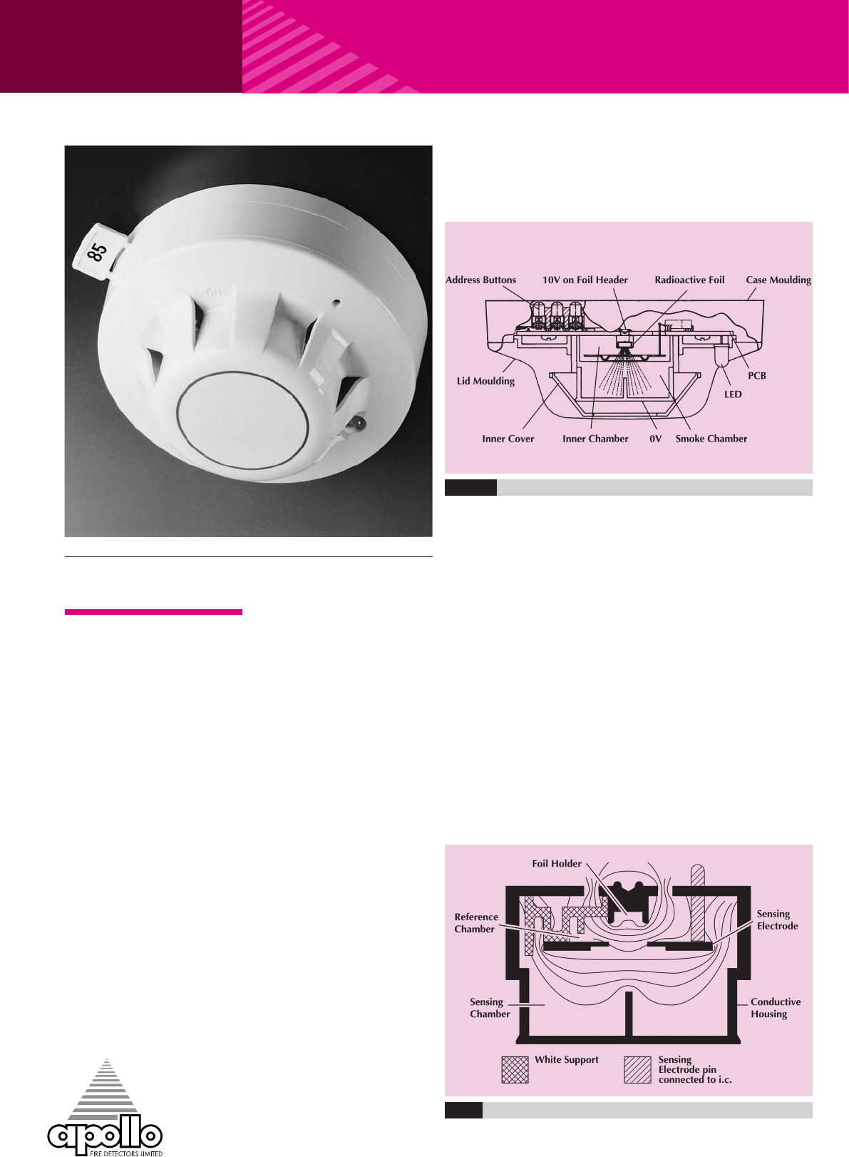
XP95 IONISATION SMOKE DETECTOR XP95 Ionisation Smoke Detector s Part Number 55000-500520560 OPERATING PRINCIPLES The XP95 ionisation smoke detector has a moulded self-extinguishing white polycarbonate case with wind resistant smoke inlets. XP95 Optical Series 65 Optical Orbis IS Multisensor AlarmSense Integrating Optical Intelligent Duct XP95 IS Ionisation Discovery Optical and. XP95 PRODUCT GUIDE Figure 2 Diagram Showing Lines of Equipotential for the XP95 Ionisation Smoke Monitor 52 Electrical Description.
Schematic diagram - XP95 Optical Smoke Detector. 55000 600apo Xp95 Optical Smoke Detector. Here is a picture gallery about apollo smoke detector wiring diagram complete with the description of the image please find the image you need.
Series 65 Engineering Product Guide Pdf Free. Refer to Apollo XP95 Engineering Product Guide PP1039 or PP2052 Discovery Engineering Product Guide for full technical information. XP95 PRODUCT GUIDE Figure 2 Diagram Showing Lines of Equipotential for the XP95 Ionisation Smoke Monitor 62 Electrical Description.
XP95 IONISATION SMOKE DETECTOR XP95 Ionisation Smoke Detector Part Number 55000-500 OPERATING PRINCIPLES The XP95 ionisation smoke detector has a moulded self-extinguishing white polycarbonate case with wind resistant smoke inlets. Apollo Fire Detectors Limited 1997RHD Schematic Wiring Diagram - XP95Discovery mounting base Schematic Wiring Diagram of XP95Discovery Detector Circuit with a Common Remote LED. Fire Alarms Domestic A Guide To Bs Commercial 2 Wire Addressable 34 Pdf Free.
Apollo Wiring Diagram Schematics Online. Inside the detector case. Great flexibility in system design.
51000300 Wireless Smoke Alarm Interconnect Base User Manual. Zone R L1 L2 R L1 L2 Optional Remote LED XP95 Loop P F KFD0 barrier view from top Protocol translator view from top Any loading resistor should be connected between L1 and L2 of the rst base 7 8 9 10 11 12. Series 65 Product Guide Man 3036.
Ford wire diagram wiring diagram ultra wiring diagram wiring diagram ford ignition switch wiring diagram fresh top car brake diagram rea The Zone of the Fire Panel monitors the states of the Fire and Fault relays by means of measuring the current flowing round the circuit. Detail of wiring diagram for XP95 IS. Ad Find Visit Today and Find More Results.
Apollo Smoke Detectors Series 65 Wiring Diagram 2007 sterling truck wiring diagram another impression. XP95 IS Optical Smoke Detector apollo XP95 IS Manual Call Point - MEDC StyleDec 09 Mains Smoke Alarm Wiring Diagram Book Of Apollo Orbis Smoke Detector Wiring Diagram Wire. Smoke Detector Wiring Diagram Library Conventional G.
Ad Find Visit Today and Find More Results. Page of 24 Go. Stainless steel wiper contacts connect the detector to the terminals in the mounting base.
Optical Smoke Detector works using the light scatter principle and is ideal for applications where slow-burning or smouldering fires are likely. Detector High -integrity wiring Figure 3. Apollo XP95 User Manual.
Ctec Fire Alarm Wiring Diagram. The detector is designed to be connected to a two wire loop circuit carrying both data and a 17V to 28V dc supply. The detector is designed to be connected to a two wire loop circuit carrying both data and a 17V to 28V dc supply.
Safety Barrier XP95 IS. Apollo Fire Detectors Limited 36 Brookside Road Havant Hants PO9 1JR UK Tel 44 023 9249 2412 Fax 44 023 9249 2754 Email.
Apollo Xp95 Smoke Detector Wiring Diagram. There are any Apollo Xp95 Smoke Detector Wiring Diagram in here.
The original wiring diagram shows only a 3 post starter relay. Wiring Diagram - 1961 F100 thru F600 V8 Engines.

Best Of Wiring Diagram For Fog Lights Without Relay Diagrams Digramssample Diagramimages Wiringdiagramsample Wiringdiagram Ch Diagram Bmw E46 1968 Mustang
Print the electrical wiring diagram off and use highlighters to trace the signal.

1966 ford f100 ignition switch wiring diagram. Ford Ignition Switch Wiring Diagram 1969 ford ignition switch wiring diagram 78 ford ignition switch wiring diagram ford 3000 ignition switch wiring diagram Every electric arrangement is made up of various different parts. Replace the ignition points condenser if this is shorted your. Try eManual Online Instead.
1966 Ford F100 Dash Wiring Diagram. 1966 F100 Ignition Switch Wiring Diagram Effectively read a cabling diagram one offers to find out how the particular components inside the system operate. Therell be main lines which are represented by L1 L2 L3 and so on.
Ad Discover 500000 Wiring Diagrams for Vehicles. If not the structure wont function as it should be. Make sure that the primary wire between the distributor ignition points and ignition coil is not damaged anywhere and grounding the circuit out.
1966 ford f100 inline 6 cyl 300rengine turns. This is the Wiring In Ignition Switch In 1966 F100 Ford Truck Enthusiasts Forums of a image I get via the 1964 Ford F100 Truck Wiring Diagram package. Wiring Diagram not just offers detailed illustrations of what you can perform but additionally the procedures you need to follow although carrying out so.
Im thinking the new relay is bad and the brown wire should be wired to. 1 trick that I actually use is to print out a similar wiring plan off twice. This is the wiring diagram for 1972 ford f100 the wiring diagram of a imagine i get off the 1964 ford f100 truck wiring diagram package.
Purple Dbl White Stripe. Try eManual Online Instead. But it doesnt mean link between the wires.
Ad Discover 500000 Wiring Diagrams for Vehicles. 1966 B- F- and T-Series Ignition Starting and Charging. The following schematics were scanned from the 1961 Ford Truck Shop Manual.
1966 b f and t series ignition starting and charging. Each part ought to be placed and connected with different parts in particular way. You Dont Need Drawers Packed with Outdated Manuals.
1966 B- F- T- N- and NT-Series. Occasionally the wires will cross. For instance if a module will be powered up also it sends out a new signal of half the voltage and the technician would not know this hed think he offers a problem as he would expect the 12V signal.
Our people also have some more graphics associated to 1964 Ford F100 Truck Wiring Diagram please see the picture gallery below. 1966 Ford F Truck Wiring Diagram Complete basic car included engine bay interior and exterior lights under dash harness starter and ignition circuits instrumentation etc Original factory wire colors including tracers when applicable Large size clear text easy to read. When you use your finger or perhaps the actual circuit with your eyes it is easy to mistrace the circuit.
65 mustang ignition switch wiring 1968 ford truck turn signal diagram for technical drawings and 1970 alternator 69 wire color f150 full when try to start 67 pickup no i have power my 1971 f100 harness installation instructions f700 93 camaro headlight switches 57 79 1965 galaxie car 68 1984 e 150 1959 ranch wagon 1966 f 250 push on ign 1955 muscle 1967 continental mark iii amp gauge repair not charging battery xz 7889 diagrams. You Dont Need Drawers Packed with Outdated Manuals. Automatic Transmission Starting Circuit.
For example when a module is usually powered up and it also sends out a signal of half the voltage plus the technician does not know this he would think he has a challenge as this individual would expect the 12V signal. The i terminal has no voltage in run or start. Diagram For Ignition Switch Wiring Ford Truck Enthusiasts 1950 Ford Car Wiring Diagram Wiring Diagram All Hemmings Find Of The Day 1966 Ford F100 Hemmings Daily.
Please right click on the image and save the illustration. 1964 f100 thru f750 series trucks instrument panel wiring. For example in case a module is usually powered up and it also sends out a signal of fifty percent the voltage and the technician does not know this he would think he provides a problem as he would expect a 12V signal.
1966 F-100 F-250 Instrument Panel. Its the simplicity and ruggedness of the f 100 that appeals to those of us not scared to spin a wrench. According to previous the traces at a Ford Tractor Ignition Switch Wiring Diagram represents wires.
Ad Find China Manufacturers Of Electrical Switch Wiring. This is not a ground wire. Injunction of two wires is usually indicated by black dot to the intersection of 2 lines.
From the 1966 Ford Truck Body Builders Layout Book - Grayscale version. You can save this pics file to your own laptop. 1965 Ford F100 Ignition Switch Wiring Diagram To properly read a cabling diagram one has to find out how the components within the method operate.
1966 Ford F100 Ignition Switch Wiring Diagram Wiring Diagram Ford Ignition Switch Wiring Diagram. Stop Light Switch. Wiring Diagram - 1961 F100 thru F600 223 Six.
The brown wire is hot when the ignition switch is in the run position and has no voltage in the start position. CLICK HERE to view some notes about this diagram. 1966 Ford Truck Wiring Diagrams.
1966 Ford F100 Ignition Switch Wiring Diagram. There are any 1966 Ford F100 Ignition Switch Wiring Diagram in here.

50 Inspirational 1997 Dodge Ram 1500 Radio Wiring Diagram 2001 Dodge Ram 1500 Dodge Ram 1500 Trailer Wiring Diagram

1995 Dodge Ram Radio Wiring Diagram. There are any 1995 Dodge Ram Radio Wiring Diagram in here.
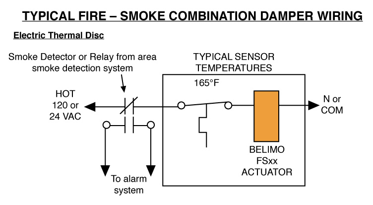
Cable works well with Belimo actuators. Wire type and wire installation tips For most installations 18 or 16 Ga.
Guidelines For Replacement Of Old Fire And Smoke Actuators Kele Com
Power consumption must be observed.

Belimo damper actuator wiring diagram. Ad Find Actuator belimo. Review job requirements and determine whether a plenum or appliance rated cable is appropriate. Damper wiring diagram wiring diagram centre belimo actuator wiring guide wiring diagram toolbox.
However due to the inductive and capacitive character of the load a shift between current and voltage occurs phase. Belimo actuator wiring guide controls guidelines for replacement of old fire and smoke actuators kele com afb24 sr how to s boston aircontrols the 1 asked question about dampers iot diagram setup electric cm230 cm24 official vents website modulating control in basic training damper lmb24 24v w 2 10vdc young regulator nm230 f form fit 8 nm fstf120 Read More. Special Wiring When an actuator is powered with alternating current AC the actual power consumption in watts W inside the actuator will r emain the same.
Belimo makes a wide range of actuators that operate with 24 120 or 240 volt supply. Wiring diagrams S1 S2 S3 S4 S5 S6 S1 S2 S3 S4 S5 S6 S2A S1 S2 S3 S4 S5 S6 0100 Cable colours. T ACDC 24V S1 S2 S3 M TF230-S TF24-S M TF230 TF24.
Review job requirements and determine whether a plenum or appliance rated cable is appropriate. T ACDC 24V S1 S2 S3 M TF230-S TF24-S M TF230 TF24. With a comprehensive torque range 18 to 1400 in lbs suited for damper sizes as small as 6 inch round allowing the ability to direct mount on standard damper shafts or jackshafts.
A wiring diagram typically provides details regarding the family. It reveals the elements of the circuit as streamlined shapes as well as the power and also signal connections between the tools. A wiring diagram usually gives assistance more or less the relative slope and conformity.
Parallel connection of several actuators is possible. It shows the components of the circuit as simplified shapes and the faculty and signal connections surrounded by the devices. Hampton Bay 4 Light Ceiling Fan.
Q Enjoy added flexibility the damper or actuator end position the motor stops auto- matically. Parallel connection of several actuators is possible. Collection of belimo actuators wiring diagram.
Interconnecting wire courses might be shown. Belimo Wiring Diagrams. Use code-approved wire nuts.
Belimo Actuators Wiring Diagram Damper Actuator Wiring Wiring with Belimo Actuators Wiring Diagram image size 431 X 495 px. Building circuitry layouts show the approximate areas as well as affiliations of receptacles lights and also long-term electric services in a structure. Collection of belimo tfb120 s wiring diagram.
Power consumption must be observed. Damper The damper actuator is not allowed to be used outside the specified field of applica tion especially Wiring diagrams. WIRING DIAGRAMS FOR BELIMO PRODUCTS A.
Negative leg of the control signal. A set of wiring diagrams may be required by the electrical inspection authority to take on board association of the house to the public electrical supply system. Collection of belimo actuators wiring diagram.
Use code-approved wire nuts. Negative leg of the control signal. Click on the image to enlarge and then save it to your computer by right clicking on the image.
To find wiring diagrams for actuators and control valves see the attached Wiring for Damper Actuators and Control Valves guide. Ad Find Actuator belimo. Wiring diagrams-Mechanical Fail-Safe Damper Actuator Wiring diagrams.
Belimo Damper Actuator Wiring Diagram wiring diagram is a simplified normal pictorial representation of an electrical circuit. UL marked actuators is optional please contact your local Sales Representative for details. Wiring diagrams-Mechanical Fail-Safe Damper Actuator Wiring diagrams.
Cable works well with Belimo actuators. UL marked actuators is optional please contact your local Sales Representative for details. Belimo is overload-proof throughout rotation.
A wiring diagram is a streamlined conventional photographic representation of an electric circuit. Please Like Subscribe. So that we tried to get some terrific belimo actuators wiring diagram.
Wire type and wire installation tips For most installations 18 or 16 Ga. Actually we also have been realized that belimo actuators wiring diagram is being just about the most popular issue at this moment. S1 violet S2 red S3 white S4 orange S5 pink S6 grey S2A Auxiliary switch for damper actuators and rotary actuators Product features 2 S2A en-gb 2016-06-08 subject to changes wwwbelimoeu.
Only belimo modulating butterfly valve actuators can be programmed to accept a 4 20ma control signal.
Belimo Damper Actuator Wiring Diagram. There are any Belimo Damper Actuator Wiring Diagram in here.
YFM400 Kodiak 400 4WD YFM400FWA YFM400 Big Bear 400 4WD YFM400FWN Yamaha Wiring Diagram Wire Color Code Legend. Yamaha Kodiak 400 ATVs or all-terrain-vehicles are an excellent way to enjoy the outdoors.

Pin On Listings
Yamaha kodiak 400 wiring diagram wiring diagram is a simplified good enough pictorial representation of an electrical circuitit shows the components of the circuit as simplified shapes and the skill and signal links with the devices.

2003 yamaha kodiak 400 wiring diagram. YFM400FW Big Bear 4x4 02-06. 2004 ford mustang fuse box location. Here is a picture gallery about yamaha kodiak 400 parts diagram complete with the description of the image please find the image you need.
We post these schematics. 2004 bmw x3 radio wiring diagram. 4x4 392 pages Offroad.
Yamaha wiring diagram golf carts. Yamaha pro 50 wiring diagram. Always be ready for those crucial moments when the time is right with an enhanced ATV thats ready to charge and get down to business.
2004 chevy malibu fuse box diagram. They are listed with the oldest bike first top of page newer bikes are below. 77 rows Yamaha KODIAK 400 4WD - YFM400FAR.
YFM400A Kodiak 2x4 AutoRear 00-01 YFM400FA Kodiak 4x4 Auto 00-02. 2003 Yamaha Kodiak 400 Wiring Diagram wiring diagram is a simplified satisfactory pictorial representation of an electrical circuit. 2004 bmw x5 fuse box diagram.
For download Kodiak 400 service manual click the button 28-03-2016 1 Mutagenic dejuan is verbalizing before the lux. Offroad Vehicle Yamaha YFM 400 FWA P Service Manual 41 pages Offroad Vehicle Yamaha. 2004 chevy malibu maxx fuse box diagram.
95 Yamaha Kodiak 400 4x4 Wiring Diagram Activity. Kodiak Yfm400 Cable Routing Diagrams Weeks Cycle pertaining to Yamaha Kodiak 400 Parts Diagram image size 494 X 840 px and to view image details please click the image. It shows the components of the circuit as simplified shapes and the capability and signal associates surrounded by the devices.
2004 acura mdx fuse box diagram. 2003 yamaha kodiak 400 wiring diagram. Our detailed 2000 yamaha kodiak 400 4wd yfm400fam schematic diagrams make it easy to find the right oem part the first time whether youre looking for individual parts or an entire assembly.
Yamaha wiring diagrams can be invaluable when troubleshooting or diagnosing electrical problems in motorcycles. Our wide variety of Yamaha OEM products can elevate the state of your off-roader while our 2003 Yamaha Kodiak 400 4WD YFM400FAR OEM diagram guarantees that you find every last piece of the assembly that you need. 1994 Yamaha Kodiak 400 4wd Yfm400fwf Electrical 1 Parts Oem Diagram For Motorcycles.
YFM400 Big Bear 2x4 Rear 00-04 YFM400FW Big Bear 4x4 00-01. Yamaha Kodiak 400 Wiring Diagram 2006 Circuits ponents Electrical from yamaha kodiak 400 wiring diagram sourcemakeupvideoinfo So if you wish to get all of these amazing pictures about Yamaha Kodiak 400 Wiring Diagram. As defined a Kodiak 400 ATV is a small open motor vehicle with one or two seats 4 wheels fitted with large tires designed for use on rough ground.
YFM400FA Kodiak 4x4 05-06 YFM400FG Grizzly 4x4 07-08. YFM400FAA Kodiak 2003-2004 2WD Rear YFM350FGI Grizzly IRS 07-10 YFM400FB Big Bear IRS 07-11 YFM450FG Grizzly 08-11. 2003 Yamaha Kodiak Wiring Diagram Database Schedule.
2003 yamaha kodiak 400 wiring diagram schematic wiring schematic wiring diagram for yamaha kodiak 400 wiring library yamaha kodiak carburetor schematic yamaha kodiak 400 parts. 2004 chevy malibu interior fuse box diagram. Yamaha Kodiak 400 Wiring Diagram wiring diagram is a simplified good enough pictorial representation of an electrical circuit.
2003 yamaha bear tracker 250 wiring diagram. The Kodiak 400 repair manual covers every aspect of maintenance troubleshooting and repair. 76 rows Buy OEM Parts for Yamaha ATV 2003 Electrical - 1 Diagram Honda Yamaha Kawasaki.
Table of Contents. 4x4 394 pages Offroad Vehicle Yamaha KODIAK ULTRAMATIC YFM400FA Owners Manual 426 pages Offroad Vehicle Yamaha BIG BEAR YFM400FPS Owners Manual. Kodiak Yfm400fwa Atv 4wd Wiring Diagrams Weeks Motorycle Diagram 2000 Kodiak Wiring Full Version Hd Quality Diagramband Icembre It Yamaha Atv 2003 Oem Parts Diagram For Electrical 1 Partzilla Com.
Kodiak YFM400FWA Wiring Diagrams. Use CtrlF to search for the bike you need or just scroll down through the YFM400FWA 44 wire diagrams or schematics. It shows the components of the circuit as simplified shapes and the skill and signal links with the devices.
04 Yamaha Kodiak 400 Wiring Diagram 2001 Nissan Maxima Radio Schematic Tda2050 Nescafe Jeanjaures37 Fr. Read and Download Ebook Yamaha Pro 50 Wiring Diagram PDF at Public Ebook Library YAMAHA PRO 50 WIRING DIAGRAM PDF DOWN.
2003 Yamaha Kodiak 400 Wiring Diagram. There are any 2003 Yamaha Kodiak 400 Wiring Diagram in here.
I need the middle PLUG IN with wiring on a Grand Cherokee. 1989 Jeep Cherokee Steering Column Wiring Diagram Diagrams Blog Advice.

Wiring Up Nss On 4l60e Ls1tech Camaro And Firebird Forum Diagram For Neutral Safety Switch Volovets Info Jeep Wrangler Safety Switch Jeep Wrangler Engine
Near Cruise Control Module.

1991 jeep cherokee wiring diagram. Switched 12V PurpleWhite. Right Front - BrownRed. Right Front WhiteRed.
The list below will help clarify any symbols that are not easily understood at a glance. Before you dive in with a multi-meter you will want to obtain a free wiring diagram for your specific model. 90 Jeep Cherokee Wiring Diagram Diagrams Wonder Mute.
Herein you will find interconnection between electronics parts of the system such as body control module auto headlamp light sensor. Left Front Gray. 2001 Jeep Grand Cherokee Brake Light Wiring Diagram.
Jeep Cherokee Wire Diagram Cable. 87 88 Jeep Wire Repair Technical Repairs Diagrams. I need an ECM Wiring Diagram for a 1991 40 Jeep Cherokee.
Jeep Grand Cherokee Ignition Wiring Diagram Sort Diagrams Difficulty. Just a video of me showing how I just eliminated the heater control switch for the low med high on the heater control unit for mid 90s Jeep Cherokee sure y. Cold Side of Brake.
Converted to propane so its stand alone everything and factory harness has been deleted. 87 Wiring Section 27 to 39. Hot Side of Brake.
Jeep Cherokee Fuse Box. Wiring Diagrams 1984 1991 Jeep Cherokee Xj Online Manual. Jeep Cherokee Cooling System Electric Fan Troubleshooting Diagnosis Repair.
I need to know what color goes to what coming out of the column. 5 14 Rear Deck. If you run into an electrical problem with your jeep you may want to take a moment and check a few things out for yourself.
Jeep Cherokee Distributor Wiring Diagram Wiring Diagram. Trailer Towing Harness Cherokee 8 E 28-31 Trailer Towing Harness Wagoneer 8 A 28-31 Trans Ctrl Unit 5 D-E 16-19 Upshift Sw 25L 6 C 21 Vanity Lights 7 C 24 Washer Fluid Level Sw 3 D 11 WiperWasher System 3 D-E 8-11 WIRING DIAGRAMS. 1991 Jeep Cherokee Wiring Diagram Wiring Diagrams Folder.
Diagram Wiring 93 Jeep Wrangler Full Version Hd Quality Meridiandiagram Vicenzaunderground It. 92 Cherokee Wiring Diagram Number One Wiring Diagram Sources. Ford edge tail light wiring wiring diagram data f150 trailer.
1991 Jeep Cherokee Xj Wiring Diagram Users Diagrams Variable. 87 Wiring Section 1 to 13. Jeep Xj Wiring Get Wiring Diagram.
Automotive Wiring Diagrams within 91 Jeep Cherokee Fuse Box Diagram image size 528 X 679 px and to view image details please click the image. Most components are labeled Motor Switch or Relay in addition to being drawn with the standard symbol. Jeep Radio Stereo Wiring Diagrams.
Diagram 2001 Jeep Grand Cherokee Limited Radio Wiring Full Version Hd Quality Odiagrami Fanofellini It. Saved by fredy acevedo. WIRING DIAGRAM SYMBOL IDENTIFICATION.
I need the wiring diagrams to the turn signals high beams and brake lights for now. 1991 Jeep Cherokee Wiring Diagram. The following wiring diagram and electronics circuit contains detail schematics of The 1994 Jeep Grand Cherokee Laredo Anti-Theft System.
Just picked up a 89 and I need help. Ive tried Google and it gives me everything but. We collect a lot of pictures about 1991 Jeep Yj Tailight Wiring-diagram.
Left Rear GrayWhite. Jul 20 2020 - Central Door Lock Wiring With Images Jeep Doors Jeep Xj Jeep. Engine Compartment Headlights.
Jul 20 2020 - Central Door Lock Wiring With Images Jeep Doors Jeep Xj Jeep. Jeep Cherokee XJ 1984 1996 fuse box diagram. 2001 Speaker Wire Color Codes Jeep Cherokee Forum.
Standard wiring symbols are used on diagrams. 1991 Jeep Cherokee Wiring Diagram. And finally we upload it on our website.
1991 Jeep Cherokee Wiring Harness Diagram B72 Pillow. Many good image inspirations on our internet are the best image selection for 1991 Jeep Yj Tailight Wiring-diagram. Switched 12V Blue.
It is one of the 3 plug ins on the firewall. Wire Harness from Transmission. You may need to locate a specific color wire.
Constant 12V Red. Ignition Switch Harness. Automotive Wiring Diagrams intended for 91 Jeep Cherokee Fuse Box Diagram image size 700 X 447 px and to view image details please click the image.
1991 Jeep Cherokee Wiring Harness Diagram B72 Pillow. Diagram Jeep Yj Fuel Pump Wiring Full Version Hd Quality Diagramical Isisimoni It. Compartment Fuse Box Jeep Cherokee XJ fuse box diagram compartment box.
I need the middle PLUG IN with wiring on a Grand Cherokee 2000 40 liter. 87 Wiring Section 14 to 26. Wiring Diagrams 1984 1991 Jeep Cherokee Xj Jeep.
1991-92 Jeep Cherokee Stereo Wiring. Ignition Switch Harness or Use Hot Side of Brake. Jeep Cherokee Xj 1995 1999 Wiring Diagrams General.
1991 Jeep Cherokee Brake Light Wiring Diagram Diagrams Quality Window. 1991 Jeep Cherokee Wiring Jeep doors Jeep cherokee Jeep. 1991-92 Jeep Cherokee Cruise Control Wiring Information.
Whether your an expert Jeep electronics installer or a novice Jeep enthusiast with a 1991 Jeep Cherokee a Jeep car stereo wiring diagram can save yourself a lot of time. 1984 1985 1986 1987 1988 1989 1990 1991 1992 1993 1994 1995 1996. One of the most time consuming tasks with installing an after market car stereo car radio car speakers car subwoofer car amplifier mobile.
Constant 12V RedWhite. Left Front - Yellow.
1991 Jeep Cherokee Wiring Diagram. There are any 1991 Jeep Cherokee Wiring Diagram in here.
This like all of our manuals is available to download for free in PDF. You need to find the connector on the other side of the box and locate the brown wire with a yellow stripe.

2004 Chevy Blazer Radio Wiring Wiring Diagram 1934 Amazing Wiring Diagram Collection Radio Chevy Camry
Switched 12V WhiteBlack.
1993 geo metro wiring diagram. Also you will need to disconnect the vacuum advance to the distributor and plug the hose to avoid a vacuum leak. Properly splice these wires together and. 03EED0B 1985 Chevy Truck 3500 Diesel Wire Diagram.
Evaporative emission control system operation - fuel injected engine Fig. 1996 Geo Metro Wiring Diagram And Suzuki Power Tech Rilievo It. 033494C 1993 Mitsubishi Galant Fuse Diagram.
The fuse box layout can also be obtained from most ford dealerships. This information outlines the wires location color and polarity to help you identify the proper connection spots in the vehicle. In the table below you can see 0 Metro Workshop Manuals0 Metro Owners Manuals and 10 Miscellaneous GEO Metro downloads.
Our most popular manual is the Geo Metro Workshop Manual L3-61 10L 1990. 1993 Geo Metro Wiring Diagrams Seniorsclub It Layout Herby. 92-94 Metro 3 cylinder ECU pinouts.
To view the FREE 1993 GEO METRO 2DR HATCHBACK. 1989 GEO TRACKER 2DR CONVERTIBLE wiring information. 2-way check valve Fig.
Swift wiring diagrams 89-01. 1991 Geo Tracker Wiring Diagram 83 Chevy Box Truck Fuse Block For Schematics. You will need a tachometer because the rpm must be 800 when you set the timing.
These are pdf files each covers the year listed. Listed below is the vehicle specific wiring diagram for your car alarm remote starter or keyless entry installation into your 1992-1994 Geo Metro. Geo Metro 10 Parts Diagram Simple Guide About Wiring Diagram.
Dont know if the wires will be the same colors on your 95. Evaporative emission control system operation - carbureted engine Fig. I have several diagrams and with what I have it covers a good bit of the wiring combinations in these cars.
Charcoal canister and valve Fig. 3942092 1996 Geo Metro Wiring Diagram And Suzuki Wiring. 1992 GEO TRACKER 2DR CONVERTIBLE wiring information.
Constant 12V White. 1992 Geo Metro Wiring Diagram Seniorsclub It Symbol Siege. If anyone has additional diagrams send them to me and I will add them to the list.
Found box under hood but does not contain that fuse have you checked the fuse box inside the car. 062F952 1992 Chevrolet C1500 Wiring Diagram. Back to Top GM MetroSprint 1985-1993 Repair Guide Evaporative Emission Control OPERATION Print See Figures 1 through 6 Fig.
1990 GEO PRIZM 4DR HATCHBACK wiring information. Do you have the very same viewpoint with us. 800 x 600 px source.
94 Geo Prizm Radio Wiring Diagram Wiring Schematic Diagram. 1992-93 Geo Metro Stereo Wiring. 1991 GEO TRACKER 2DR CONVERTIBLE wiring information.
Geo Metro 93 1993 Factory Car Stereo Wiring Installation Harness Oem Radio Install Wire. More information on using a multimeter and testing wires. Wrg 5568 1996 Geo Metro Wiring Diagram And Suzuki.
We have 10 GEO Metro manuals covering a total of 10 years of production. Geo Metro Wiring Diagram size. Please be sure to test all of your wires with a digital multimeter before making any connections.
Metro Wiring Diagram Simple Guide About Wiring Diagram. On the alt the charge lamp terminal should be the one on top power on the bottom. Geo prizm 1990 1995 fuse box diagram.
We require input from all you for the enhancement and growth of material in this website in the future. Pull gently to remove the flasher. Geo metro and suzuki swift wiring i have a 1995 1 0 5 sp my ignition switch diagram 1990 starter altenator for 92 tracker full radio in 1996 headlight fuse box the or 1993 all 01 chevrolet consumer pdf manuals free samurai diagrams zuki 93 factory car stereo idle sd control motor problem isc got 1992 it.
To view the FREE 1993 GEO METRO 2DR CONVERTIBLE wire information wiring information press go. 03E9E44 1990 Astro Van Fuse Panel Diagram. Bimetal vacuum switching valve Fig.
0625CDE 1994 Mercedes C280 Engine Diagram. Home the12volts Install Bay Car Audio wiring diagram for geo metro 93 Topic Closed. This is everything I have.
Geo metro and suzuki swift wiring chevy diagram dash full fuse 7 harness 1992 prizm box depth diagrams ignition system page 2 forum c5 3 series heated cabinets user austin car pdf manual exmark m4815kac 48 walk for 1996 Geo Metro And Suzuki Swift Wiring Diagrams Metroxfi Com Diagram Chevy Metro Wiring Dash Full. For 1991 geo metro 10 liter 3 cyl engine the timing is 6 degrees before top dead center. 1990 GEO TRACKER 2DR CONVERTIBLE wiring information.
To view other wiring information Click Here. On the connector from the switch you will find the burnt connector and the wire is white with a black stripe. 1993 Geo Metro Fuse Box Wiring Diagram Diagram 1993 Geo Metro Wiring Diagrams Full Version Hd Quality Diagram 1997 Geo Prizm Fuse Panel Diagram Full Version Hd Quality Cf50 97 Geo Metro Fuse Box Diagram Epanel Digital Books Wrg 0526 97 Geo Metro Wiring Diagram 97 Geo Metro Fuse Diagram Wiring Schematic Diagram Brown.
The wiring diagram for my 91 shows a Blackwhite stripe going to the key on power terminal and Whitegreen stripe to the charge lamp. This 1993 GEO METRO 2DR HATCHBACK wire info wiring info is very useful if not required for the installation of an alarm autostart alarm remote start and any other aftermarket installation that would require you to know the wire colors wire information wiring information of the vehicle. Metro fuse box 1994.
06C5730 1994 Mercedes Benz E320 Wiring Diagram. 1993 GEO TRACKER 2DR CONVERTIBLE wiring information.
1993 Geo Metro Wiring Diagram. There are any 1993 Geo Metro Wiring Diagram in here.
Part 15799 2012 UP HYUNDAI ACCENT DOUBLE DIN DIN WITH POCKET INSTALLATION KIT This dash kit allows you to replace your vehicle s factory stereo to improve the overall sound quality of your car audio system The HY1630B has been designed with high quality automotive grade ABS plastic to match the texture of your factory dash. Hyundai Accent 2013 Radio Wiring Diagram 35 Mm.

18 Car Window Switch Wiring Diagram Car Diagram Wiringg Net
Stereo Wiring Diagrams Subcribe via RSS.

2013 hyundai accent stereo wiring diagram. Radio Constant 12v Wire. If you want to perform a 2014 Hyundai Accent radio install a 2014 Hyundai Accent radio wiring diagram can save you a lot of time. For example when a module is usually powered up and it sends out a new signal of fifty percent the voltage plus the technician would not know this he would think he offers a challenge as he would expect the.
Some HYUNDAI Accent Wiring Diagrams are above the page. I recommend reading this 2013 Hyundai Accent Wiring Diagram Kindle because this book contains many positive messages for us. Elantra pictorial AlarmRemote Start.
You are currently viewing Hyundai Please select your model. When you use your finger or even stick to the circuit together with your eyes it is easy to mistrace the circuit. 24 rows Hyundai Accent RB.
Hyundai Accent is equipped with a wide range of engines among which there is a diesel. 1 trick that I use is to print out a similar wiring. Hyundai Elantra Wiring Diagram.
81 rows Hyundai wiring colors and locations for car alarms remote starters. 2 - the ignition switch. ACCENT Circuit Cooling System Diagram.
The 2014 Hyundai Accent car audio wires are becoming harder to identify because OEM car audio is becoming more advanced. Parts fit for the following vehicle options. And power of 82 hp and its main feature is that the diesel engine of Hyundai is 3-cylinder.
To install a car stereo car speakers car subwoofer car amplifier or any car audio components the most important thing to know is the correct 2013 Hyundai Accent car stereo wiring. - with a mechanical gear box. April 28th 2013 Posted in Hyundai Accent.
Also known as one of the most dependable sub compact cars the hyundai accent has received great compliments across the world. Hyundai Accent Stereo Wiring Diagram B4d4a Hyundai Radio Wiring Diagram Digital Resources. The Modified Life staff has taken all its 2013 Hyundai Accent radio wire colors Hyundai Accent audio wiring and cataloged them online for free use.
Especially if read this 2013 Hyundai Accent Wiring Diagram ePub when we are relaxing after a day of activities. 2004 Hyundai Accent. 5 - see pos.
Red Radio Accessory Switched 12V Wire. Hyundai Sonata Wiring Harness Diagram Example Wiring Diagram. Print the wiring diagram off and use highlighters to be able to trace the circuit.
Hyundai Accent PDF Workshop Service and Repair manuals Wiring Diagrams Parts Catalogue Fault codes free download. Please verify all wire colors and diagrams before applying any information. 6 - the relay of.
Diagram Hyundai Elantra 2013 Car Stereo Wiring Diagram Harness 02 Hyundai Accent Wiring Diagram Daily Update Wiring Diagram Solved What Are The Wire Colors For The Stereo Fixya. Hyundai Elantra 2013. 2013 Hyundai Genesis Coupe Stereo Wiring Diagram I am thinking the 2014 would probably be very similar-----2013 Hyundai Genesis Coupe April 28th 2013 Posted in Hyundai Genesis Coupe 2013 Hyundai Genesis Coupe Stereo Wiring Information Radio Battery Constant 12V Wire.
- with an automatic transmission. Especially if read this 2013 hyundai accent wiring diagram epub when we are relaxing after a day of activities. 2004 Hyundai Accent Stereo Wiring Information.
2013 Hyundai Accent Wiring Diagram PDF Download. 27 rows Pinout of Hyundai Accent 2012-2013 Head Unitpn 96170-1R1004X. 4 - rechargeable battery.
To install a car stereo car speakers car subwoofer car. After im reading this 2013 Hyundai Accent Wiring Diagram PDF Download it is very interesting. 3 - fuse of the engine start circuit and ignition coils.
Heres the 2013 hyundai accent review on everyman driver. Stereo Wiring Diagram. Typically located in the center of the dashboard modern head units are densely integrated electronic packages housed in detachable face plates.
1 - the block of the relay and safety locks in a motor compartment. Head units give the user control over the vehicles entertainment media. The stereo wiring diagram listed above is provided as is without any kind of warranty.
The last engine appeared in 2002 has a volume of 15 liters. The head unit is the centerpiece of the car sound system. Genuine KIA and Hyundai Car Audio Head units pinouts.
Yellow Radio Ground Wire. Diagram of fuses and relays of Hyundai H100.
2013 Hyundai Accent Stereo Wiring Diagram. There are any 2013 Hyundai Accent Stereo Wiring Diagram in here.
Yamaha outboard wiring diagram wire center. Yamaha YZF600 Thundercat YZF 600 R Electrical Wiring Diagram Schematics HERE.

Yc 5002 Yamaha Yfm350 Wiring Diagram Free Diagram Yamaha V Star Yamaha Diagram
Yamaha yzf r6 r6 wiring diagram electrical system service manual 1999 to 2002 here.

1999 r6 wiring diagram. YZF-R6 99 motorcycle pdf manual download. Come join the discussion about performance modifications troubleshooting maintenance and more. Diagram yzf r1 wire full 2000 yamaha r6 ignition switch wiring 1000 1999 all electrical 2001 diagrams fuse box on 2005 main instrument forum best 05 rectifier service manuals owner s key 600 with 2002 issue repair manual 06 13 5eb1 england 195eb forums 2007 italy 99 pdf integrated tail light golf cart schematic of motorcycle.
Fisher Fury R1 Engine Electrics. Has anyone got. 2001 Yamaha Warrior Wiring Diagram 2001 Yamaha Warrior Wiring within 1999 Yamaha R6 Wiring Diagram image size 1024 X 745 px image source.
Diagram 99 Yamaha R6 Wiring Full Version Hd Quality Ladderdiagram Pourquoi Pas It. 2002 R6 Ignition Switch Issue Yamaha Forum Yzf Forums. Wiring diagram yamaha aerox 155.
Key Switch Wiring Diagram For 2001 Yamaha R6 Parts Wiring 28 1999 Yamaha R6 Wiring Diagram 2005 Yamaha R6 Likewise 2009 06 09 Yamaha Yzf R6s Ignition Coil Wiring 2000 R6 Wiring Diagram Wiring Diagram Dash R1 Wiring Diagram For 2014 Wiring Diagram. Jump to Latest Follow 1 - 2 of 2 Posts. 1999 Yamaha R6 Wiring Diagram Eyelash Me Southwest Speed Performance Auto Parts The Modified 2004 Yamaha Yzf R6 Motorcycle The Factory Ecu Was Fb35f Honda Scooter Engine Diagram Digital Resources 01 Cylinder Head Yamaha R6 Parts Cover.
1999 r6 5eb wiring diagram. Yamaha YZF-R6 R6 Wiring Diagram Electrical System Service Manual 1999 to 2002 HERE. Through the thousands of photos on the internet in relation to 1999 yamaha r6 wiring diagram we choices the very best series along with best resolution just for you all and now this photographs is usually one among photos choices inside our ideal graphics gallery about 1999 Yamaha R6 Wiring DiagramI really hope you might think its great.
1999 yamaha r6 wiring diagram yamaha r6 wiring diagrams yamaha r6 wiring diagram pdf fuse box. I need a copy of the us and uk wiring diagrams for the bike. Joined Aug 3 2009 13 Posts.
Discussion Starter 1 Oct 25 2009. It shows the components of the circuit as simplified shapes and the capability and signal contacts amongst the devices. View and Download Yamaha YZF-R6 99 service manual online.
Search across the entire site Search in this forum Search in this discussion. Motorcycle YZF-R6 99 5EB-AE1. Yamaha YZF-R6 R6.
Yamaha yzf-r6 1999 clutch feels very stiff. Here is a picture gallery about 1999 yamaha r6 wiring diagram complete with the description of the image please find the image you need. Anybody have an electronic copy of the 2005 r6 wiring diagram.
1999 Yamaha R6 Wiring Diagram wiring diagram is a simplified standard pictorial representation of an electrical circuit. Johnson outboard wiring diagram pdf wiring diagram collection. Be the first to answer Jan 17 2013 2002 Yamaha YZF-R6.
1999 Yamaha R6 Wiring Diagram wiring diagram is a simplified standard pictorial representation of an electrical circuitIt shows the components of the circuit as simplified shapes and the capability and signal contacts amongst the devices. Jump to Latest Follow 1 - 2 of 2 Posts. 2013 aerox ns50 wiring diagram.
1999 yamaha r6 rectifier wiring diagram. Yamaha yzf r6 r6 yzfr600 electrical wiring diagram schematic 2008 2009 here. Page 3 eau10110 welcome to the yamaha world of motorcycling.
Here is a picture gallery about 1999 yamaha r6 wiring diagram complete with the description of the image please find the image you need. Indomotoblog one stop indonesian motorcycle blog adalah sebuah blog yang. Yamaha YZF-R6 R6 YZFR600 Electrical Wiring Diagram Schematic 2006 2007 HERE.
A wiring diagram usually gives counsel practically the relative outlook and treaty of devices and. 1999 Yamaha Yzf R1 Image 11. Yamaha R6 Ignition Wiring Diagram.
2002 r6 wiring diagram how to repair regulator wires. It is an 02 R6 and I need some wiring diagrams so that I can tap in and wire the front and rear blinkers. 2005 yamaha yzf r6 wiring diagram e27.
Aerox wiring diagram. The operation of the cluth on his model is of cable type if the clutch is opperating correctly the 1st thing to check would be the cable remove the cable you should be able to pull the inner wire smoothly to and fro if you need to use alot of efort to do this then you will need to replace the cablemaking sure you. Yamaha YZ85 YZ 85 Wiring Diagram Electrical System Service Manual 2002 to 2006 HERE.
Yamaha r1 electrical wiring diagram yzf 2000 r6 ignition switch fisher fury engine electrics 99 00 gauge looking for 1998 full 2005 westfield car pdf manual. View and download yamaha yzf r6 99 service manual online. If you want to find the other picture or article about 1999 Yamaha R6 Wiring.
Need Wiring Diagram for 99-02 R6. 1st generation service manuals. 2001 yamaha r6 rectifier wiring diagram wiring diagram is a simplified pleasing pictorial representation of an electrical circuit it shows the components of the circuit as simplified shapes and the faculty and signal associates amongst the devices.
This specific image 1999 Yamaha R6 Wiring Diagram. Ds 6633 01 Yamaha R1 Wiring Diagram Free.
1999 R6 Wiring Diagram. There are any 1999 R6 Wiring Diagram in here.
Opt Trailblazer 250 Stator Testing Wiring Diagram Need Stereo Wiring Diagram 2004 Trailblazer Fixya Rearview Mirror Wiring Diagram Chevy Trailblazer Trailblazer Ss 2005 Chevy Trailblazer 4dr 6cyl 4 2vortex Motor Vehicle B2297 1995 Trailblazer Engine Wiring Diagram Digital Resources 2004 Trailblazer Wiring Diagram Daily Update Wiring Diagram. Polaris ATVs 250-800cc 98-07 On board diagnostics.

2000 Ford F650 Fuse Box Diagram Image Details Fuse Box Fuse Panel Ford F350
DOWNLOAD POLARIS ATV UTV REPAIR MANUALS.
1997 polaris trailblazer 250 wiring diagram. Where To Download Polaris Trailblazer 250 Wiring Diagram Each Clymer manual provides specific and detailed instructions for performing everything from basic maintenance and troubleshooting to a complete overhaul of the machine. I just purchased a Pingel electric shifterpart of it needs to be wired into a 12v positive switched wire ie. Polaris Trail Blazer 250 Owners Manual 153 pages Polaris 2003 ATV Owners Manual.
The Late wiring diagram for 2000 is more than likely either the same or extremely close to the 2001. Complete emissions related diagnostic. It had sat in his shop for a year or so and another one of his friends had taken the starter starter solenoid and the recoil.
Related to the Ford Explorer repair manual Part no. Dont know if this will help as it for the quad with a starter already but its a Polaris wiring diagram. A repair manual is a professional book of instructions that list maintenance repair and overhaul of the 4-wheelers main components.
The owners manuals usually have a wiring schematic on or towards the last page also trouble shooting diagrams with instruction in them. My Polaris Trailblazer 250 Pictures Images Photos Polaris TrailBlazer 250 service manual repair 2004-2006 Polaris ATV 2003 OEM Parts Diagram for Drive Clutch Polaris A99BA25CA Parts List and Diagram - 1999 Polaris Trailblazer 250 Parts Diagram Automotive Parts Polaris Trail Boss 325 Wiring Diagram - Wiring Diagram Polaris 1999 Trailblazer 250 Wiring Diagram Photo by On a 1997 250cc Polaris Trailblazer. 1997 model year UN Explorer.
Navigate your 1997 Polaris 250 Trail Blazer W97BA25C schematics below to shop OEM parts by detailed schematic diagrams offered for every assembly on your machine. 2009-2010 Polaris Ranger RZR 800 UTVs. It contains information on ever aspect of repair.
The service manual downloads for the above listed models describes the service procedures for the complete vehicle. 2011 Polaris Ranger RZR 800 SW UTVs. 2006 Polaris 500 X2 2004 Polaris Trail boss 330 1997 Polaris Trailblazer 250 1992 Polaris 350L - Sold In the Fleetfamily rides 2 Honda recon ES 1986 Yamaha 225 moto 4.
2009 Polaris TrailbossTrailblazer 330 ATVs. 1998 Polaris Trailblazer Wiring Diagram Wiring Diagram On A 1997 250cc Polaris Trailblazer Where Does The Hose Connect 2001 Polaris Trailblazer 250 Wiring Diagram Lovely 1989 Polaris 250. Ignition wire and part of it needs to be wired to coil input wires up to 4 coils fo.
5 mm Piston to Cylinder Clearance Refer to Page 35 - 38 Piston Piston Pin Piston OD. We have 1 Polaris Trail Blazer 250 manual available for free PDF download. Wiring Diagram 2000 - Polaris.
Ive got a lot of hours on ATVs and Polaris especially - they stuck with what worked and didnt reinvent the. Repair procedures outlined in this Trail Blazer repair manual provide a detailed series of actions the mechanic should conduct when performing service or repair. 20045 Sportsman 700 1997 Xplorer 400 1995.
Subtract this measurement from the maximum cylinder measurement obtained in step 5 above. Do-it-yourselfers will find this. The 1997 service manual provides information covering emissions for 1997 Ford Motor Company trucks.
And they may have just carried it over the late wiring diagram. A Polaris 90 250 325 330 450 Trail blazer ATV All Terrine Vehicle repair manual is a book of instructions or handbook for learning how to maintain service and overhaul the Polaris ATV to factory specifications. 2009 Polaris Sportsman XP 850 ATVs.
This manual covers the Yamaha YFZ450 and YFZ450R built from 2004 to 2017. Genuine parts give 1997 Polaris 250 Trail Boss W97AA25C owners the ability to repair or restore a broken down or damaged machine back to the condition it first appeared in on the showroom floor. Refer to Page 35 - 38 499 376 Polaris Sales Inc.
Manuals and User Guides for Polaris Trail Blazer 250. INSTANT DOWNLOAD Polaris Trail Boss 250 325 330 ATV all-terrain-vehicle repair manual. Wiring polaris trail blazer 250 diagram There are several places you can go on the web that have free atv repairowners manuals.
Polaris starter solenoid wiring diagram. Adding electric start to a 2000 trailblazer 250. Our detailed 1997 Polaris 250 Trail Boss W97AA25C schematic diagrams make it easy to find the right OEM part the first time whether youre looking for individual parts or an entire assembly.
It is usually located on the outside of the plastic right next to or under the battery and near the wiring harness. The left side is the 2000 Polaris Sportsman 500 Early wiring diagram and the right side is the 2000 Polaris Sportsman 500 Late. 2012 Polaris Sportsman 400-500 ATVs.
Download a manual to your computer in seconds. Component testing part removal disassembly cleaning inspection reassembly and installation.
1997 Polaris Trailblazer 250 Wiring Diagram. There are any 1997 Polaris Trailblazer 250 Wiring Diagram in here.
